

Well, I'm no expert so this isn't going to be a nice quick "How To" thread....
I've been doing my homework, and learning as much as I can about the process so all I'm going to do is post up the pics of my struggles and document whatever learning I do along the way. Anyone with experience who wants to offer suggestions along the way is welcome to jump in here.
I'd prefer to get helpful advice even if I have to go backwards to re-do something... the alternative is to do things wrong, and I'm not interested in that.
So.... here we go:
I've got a set of 404 axles (one steer, one non-steer) and a set of Spidertrax 9" housings. I wanted to do a basic mock-up with one axle and the frame just to see what sort of clearances issues I was going to have.
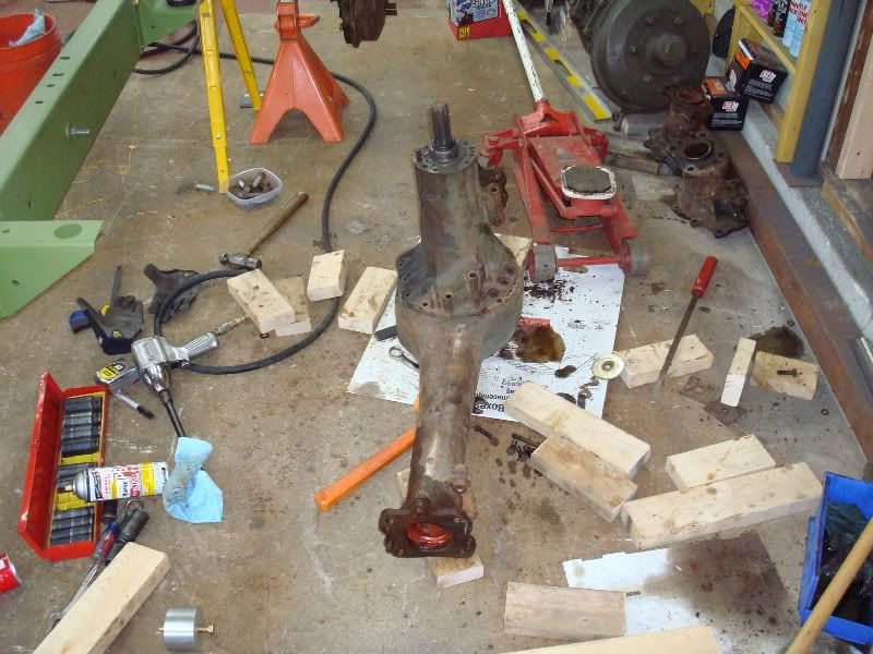
The first setback was that I didn't have a 55mm socket, or a way to generate 750Lbs of torque to remove the massive hub nuts...so I did the only other thing that I could think of:
![Image]()
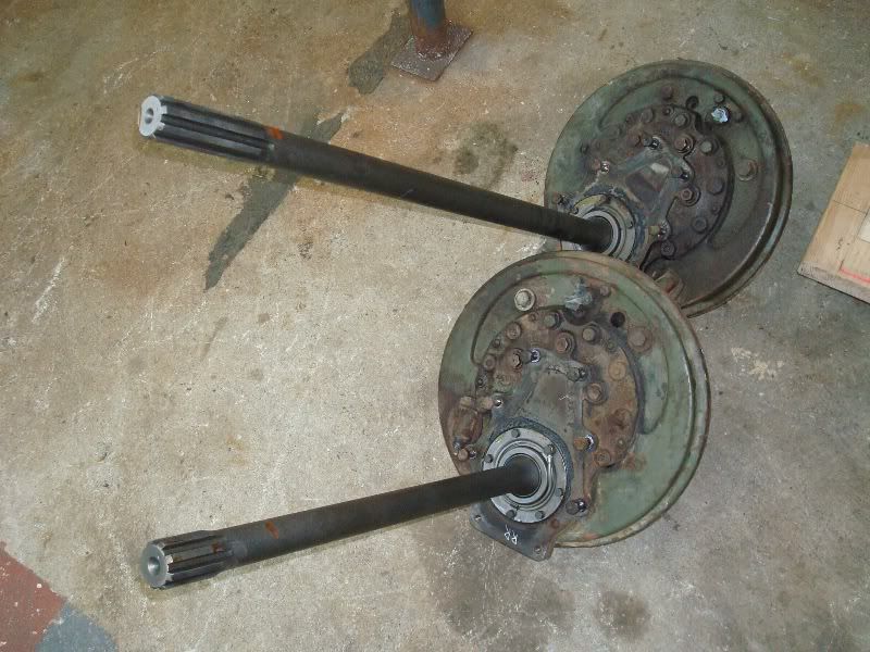
I simply unbolted the portal from the intermediate adapter on the axle housing and slid the entire drum brake / portal & inner axle off as a single unit. There is a small tube running around the perimeter of that portal bearing...looks like a brake line with a banjo fitting, but might be some sort of gear oiler?
![Image]()
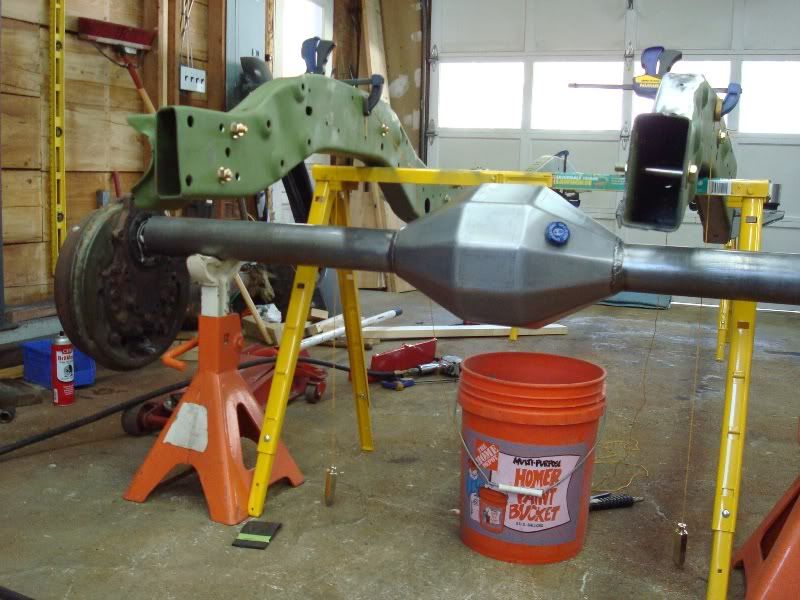
The mock up with the Spider-9 ended up looking like this. The frame is about 2" shorter than actual ride height will be, so that gives me about 8" of uptravel before I hit the frame. My assumption is that I'll crush the oilpan well before I ever make contact with the frame rails... The wheel center is at the correct height to simulate my 38" tires, and the pumpkin clearance ends up being 18"....pretty impressive.
![Image]()
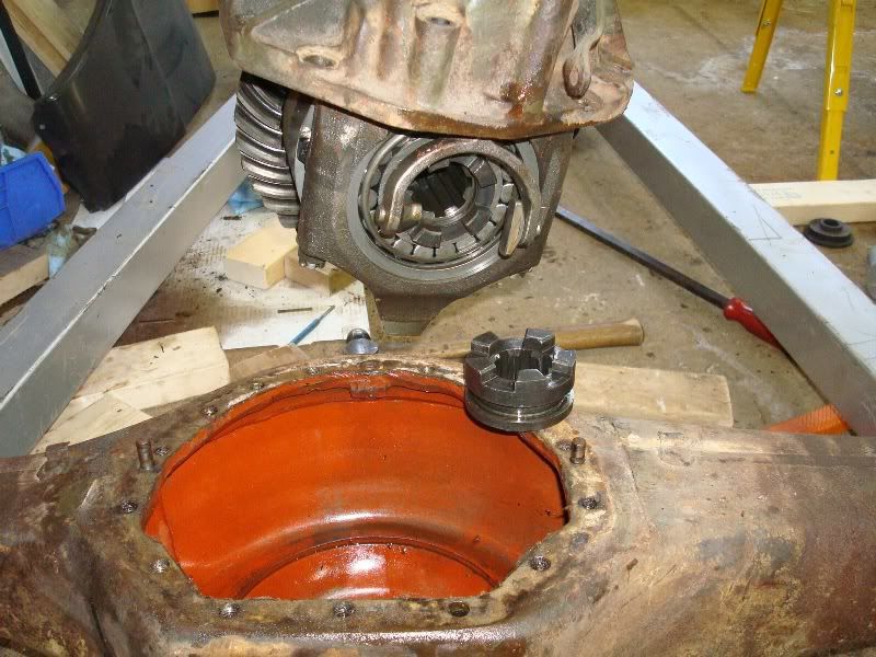
Here's a shot of the 3rd member removed. I just wanted to see how it looked and how the locker operated. It took me a while to get the 3rd removed, but a quick search on this forum told me to rotate the pig 1/4 turn toward the locker side for clearance of the ring gear. As soon as I tried that, it dropped right out.
![Image]()
I can sympathize at what a pain it must be to R & R a broken shift collar for the locker assembly. There's quite a bit of labor to get the 404 this far apart.
Last night, I jumped on eBay and picked up a Snap-On torque multiplier and a 55mm impact socket. I hate not having the right tools, and it seems like I'm going to need them quite a few more times anyway...
Now that I have those ~10" long "intermediate" axle housings removed it seems like it won't be hard to use them as a template to machine an adapter to mount to the 3.5" axle tube of the Spider-9s. I notice that some guys re-use these intermediate parts and build a flange further inboard on the axle, and other guys build their adapter to go directly to the back of the portal housing. I'm not sure if either has a particular advantage, or if it's just personal preference?
.
I've been doing my homework, and learning as much as I can about the process so all I'm going to do is post up the pics of my struggles and document whatever learning I do along the way. Anyone with experience who wants to offer suggestions along the way is welcome to jump in here.
I'd prefer to get helpful advice even if I have to go backwards to re-do something... the alternative is to do things wrong, and I'm not interested in that.
So.... here we go:
I've got a set of 404 axles (one steer, one non-steer) and a set of Spidertrax 9" housings. I wanted to do a basic mock-up with one axle and the frame just to see what sort of clearances issues I was going to have.
The first setback was that I didn't have a 55mm socket, or a way to generate 750Lbs of torque to remove the massive hub nuts...so I did the only other thing that I could think of:
I simply unbolted the portal from the intermediate adapter on the axle housing and slid the entire drum brake / portal & inner axle off as a single unit. There is a small tube running around the perimeter of that portal bearing...looks like a brake line with a banjo fitting, but might be some sort of gear oiler?
The mock up with the Spider-9 ended up looking like this. The frame is about 2" shorter than actual ride height will be, so that gives me about 8" of uptravel before I hit the frame. My assumption is that I'll crush the oilpan well before I ever make contact with the frame rails... The wheel center is at the correct height to simulate my 38" tires, and the pumpkin clearance ends up being 18"....pretty impressive.
Here's a shot of the 3rd member removed. I just wanted to see how it looked and how the locker operated. It took me a while to get the 3rd removed, but a quick search on this forum told me to rotate the pig 1/4 turn toward the locker side for clearance of the ring gear. As soon as I tried that, it dropped right out.
I can sympathize at what a pain it must be to R & R a broken shift collar for the locker assembly. There's quite a bit of labor to get the 404 this far apart.
Last night, I jumped on eBay and picked up a Snap-On torque multiplier and a 55mm impact socket. I hate not having the right tools, and it seems like I'm going to need them quite a few more times anyway...
Now that I have those ~10" long "intermediate" axle housings removed it seems like it won't be hard to use them as a template to machine an adapter to mount to the 3.5" axle tube of the Spider-9s. I notice that some guys re-use these intermediate parts and build a flange further inboard on the axle, and other guys build their adapter to go directly to the back of the portal housing. I'm not sure if either has a particular advantage, or if it's just personal preference?
.


